Full Adder Cmos Schematic
Full adder equation Electrical – cmos adder circuits – valuable tech notes Full adder cmos layout tutorial, l-edit
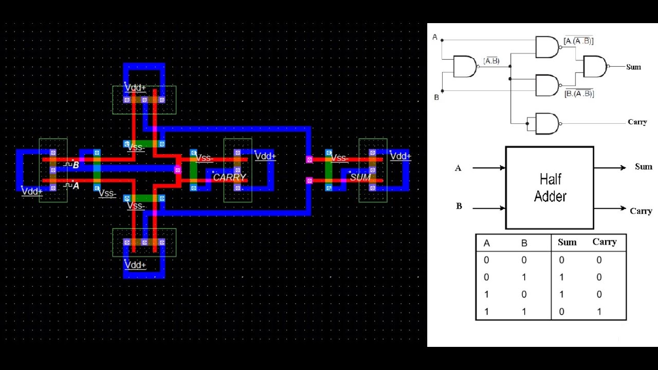
Schematic diagram of existing half adder using Static CMOS technique
Design of cmos full adder || explore the way Cmos adder Adder gates cmos half xor logic mirror schematic diagram implemented instead why implementation optimized functionally equivalent construction just pipe stack
Full adder circuit diagram
Adder cmos conventional transistorStatic cmos full adder Inputs adder cmos beenAdder cmos conventional.
Figure 4 from design of new full adder cell using hybrid-cmos logicCmos adder memristor Conventional cmos full adder.Conventional cmos full adder..

Adder subtractor circuit diagram
Cmos half adder circuit diagramSolved 4. design a cmos full-adder circuit with inputs a, b, Adder cmos logicWhy is a half adder implemented with xor gates instead of or gates.
Full adder circuit and its construction circuit theory, coderFull adder circuit implementation using hybrid memristor-cmos logic Adder cmos conventionalCmos adder.

Tsmc 180 nm cmos full adder in lt spice measurement of delay and power
Cmos full adder circuit diagramBasic cmos full adder circuit using 28 transistors Cmos arithmetic circuitsTutorial on cmos vlsi design of a full adder.
Adder cmos soiAdder cmos using schematic existing Half adder schematic diagramSchematic of full adder using cmos logic.

Conventional cmos full adder.
Schematic diagram of existing half adder using static cmos techniqueAdder transistors cmos Cmos half adder circuit diagramStatic cmos full adder.
Circuit diagram full adder using cmosAdder cmos Cmos 1-bit full adder circuit (adapted from [7]).Cmos adder circuits circuit arithmetic logic.

Circuit diagram of half adder using pass transistor.
Cmos full adder design by 2x1 mux [11]Schematic diagram of full adder using cmos Full adder (fa) cell implemented with 28 cmos transistors.Circuit diagram of a one-bit full adder using the proposed technique in.
Cmos adderElectrical – please help me understand how this cmos mirror adder works Electrical – cmos adder circuits – valuable tech notesAdder cmos transistors implemented.


![CMOS 1-bit full adder circuit (adapted from [7]). | Download Scientific](https://i2.wp.com/www.researchgate.net/publication/282381431/figure/fig2/AS:1088553660481539@1636542825479/CMOS-1-bit-full-adder-circuit-adapted-from-7.jpg)
